My job first started off with me having to research and get more information on what a transfer device looks like, how it works, etc. Once I was able to gain a firm understanding then I was to create a hierarchy task analysis and with those recorded steps we were to determine which step is the most important. With that step being acknowledged Shae and Aaron were then to simulate that in process in Jack Simulations. Not only that but to be able to get a better understanding of where the nurses pain(s) were coming from I created a survey. The end result is that we were able to cut the relief of all stress and strains on nurses lower back, neck, shoulders, and wrist by almost half. I would say that all of our work was very conclusive and met all standards an objectives that we were given this summer. Due to the fact that our graduate student left the country for almost a month set us back in work ethics just a little but non the less we still managed to present an outstanding and pretty referable information. Everything on my end was completed. I will take away the memories that I gained with my fellow co-workers and as well as graduates students and staff! This experience is one that I will never forget and has opened many more doors for me. The only advice I have to offer is don't rush your time away. Utilize all of your time because deadlines will sneak up on you and you WILL have to present no matter what you have prepared. Oh and of course ENJOY THIS AMAZING EXPERIENCE!!!! It was such a pleasure to have encountered each and every REU and I wish you the best of luck in your future endeavors!!
PEACE, LOVE, AND HAPPINESS!!
Kiffinae D. Sanders
Friday, August 8, 2014

Synopsis of the Strain Energy Accumulator Research
Hello all!
This summer has gone by too quickly, but it has been an awesome ride here in Nashville. As a research team, we have grown closer together as friends, as well as make ample progress to our goals for the summer. They have been great to work with and are some of the sharpest tools in the shed!
Research Results
The purpose of my research this summer, was to prove that conductive elastomers can successfully be used to monitor damage inflicted upon them. The material that is in development for use in the Strain Energy Accumulator will need to successfully determine if critical damage has been inflicted. To prove this, we tested an on-the-market conductive elastomer. The following tests were performed:
 This polypropylene tube is filled with hydraulic fluid and begins to balloon, much like an animal ballon. The energy is stored in the strain of the elastomeric material and can be harvested during discharge.
Closing
I would like to thank the CCEFP, Dr. Adams, Dr. Barth, and the rest of my research team for giving me the resources that I needed to complete my research this summer! The experience for myself was wonderful and is something that I will take with me through out my life and career. Living in Nashville has been a blessing, and I have met some amazingly talented and respectable people along the way. Again, thanks for everything. I look forward to seeing all of my fellow REU's in our future careers, and I hope to stay in contact.

This summer has gone by too quickly, but it has been an awesome ride here in Nashville. As a research team, we have grown closer together as friends, as well as make ample progress to our goals for the summer. They have been great to work with and are some of the sharpest tools in the shed!
Research Results
The purpose of my research this summer, was to prove that conductive elastomers can successfully be used to monitor damage inflicted upon them. The material that is in development for use in the Strain Energy Accumulator will need to successfully determine if critical damage has been inflicted. To prove this, we tested an on-the-market conductive elastomer. The following tests were performed:
1) Damage Infliction -- we purposefully scratched and cut the material to measure resistance changes. The results formulated gave us insight into how the material shows promising directional sensing abilities. This is shown especially with the vertical abrasion, which permanently eliminated conductance in the material.
2) Tensile Test -- a test rig was configured to observe how the resistance changes with increasing load, as well as the hysteresis and Mullens effects of the elastomer. This test yielded repeatable results and really gave me insight into how conductive elastomers will actually react in an application
This research successfully proved that elastomers can be used practically when sensing applications are necessary! Though the research did give our team a proof-of-concept, the material tested has many shortcomings for our application including: deficient durability, single sided conductance (conductance only on surface level of the elastomer), and conductance at only small strains (< 100%).
Future Work
A couple of trials are going to be done with this conductive material. The research team will adhere a rectangular specimen to the current Strain Energy Accumulator design, with attached leads to monitor resistance changes through out charge and discharge. Secondly, a specimen will be glued to a elastomeric sample during tensile testing on an MTS machine. Each of these experiments will gives us insight into the reactions that can be expected in practical applications. Here is a picture of our accumulator that was made this summer:
Closing
I would like to thank the CCEFP, Dr. Adams, Dr. Barth, and the rest of my research team for giving me the resources that I needed to complete my research this summer! The experience for myself was wonderful and is something that I will take with me through out my life and career. Living in Nashville has been a blessing, and I have met some amazingly talented and respectable people along the way. Again, thanks for everything. I look forward to seeing all of my fellow REU's in our future careers, and I hope to stay in contact.
Thursday, August 7, 2014
Final Post - Don
Hello everyone,
It has been a great summer. There is no doubt about that. Here is a summary of everything I have been working on this summer.

It has been a great summer. There is no doubt about that. Here is a summary of everything I have been working on this summer.
Gas-Power-Cycle-Specific
Pulley Optimization for a Walking-Engine-Actuated Active Ankle-Foot Orthosis
Donald H. Kuettel III MSOE REU 2014
Outcome
The main
goal of this research was to help people with disabilities regain natural
walking ability by replicating the normal walking gait of a human through the
use of a walking-engine-actuated active ankle-foot orthosis (AAFO). This was
done using an internal-combustion engine and pulley system to reproduce the
moment experienced at the ankle during gait. Through this research, the optimal
pulley geometry was determined for the AAFO, but had a very complicated
geometry.
Impact/Benefit
Active orthotic devices for joint articulation have a vast
number of applications that could benefit many people. Individual examples of
this include: joint articulation for people suffering from disabilities,
increased load carrying capacity and walking distance for humans, and gait
training applications. The
results of this research provided insight and laid
the groundwork for future experiments for
the further development of un-tethered, compact, lightweight, efficient,
long-lasting, and safe AAFO devices.
Explanation
This research investigated the
optimization of a pulley system for the primary actuator of an AAFO utilizing a
high-efficiency pneumatic “Walking Engine”. The AAFO’s internal-combustion (IC)
engine was characterized using a dual-combustion (limited-pressure)
gas-power-cycle model. Using the dual-combustion model, both a pressure-volume
diagram and the thermodynamic engine efficiency were calculated. The moment
experienced at the ankle due to the AAFO was calculated using the pressures in
the AAFO engine. By finding the pressure in the AAFO engine as a function of
time and multiplying it by the cross-sectional area of the actuator piston, the
force output of the engine was then determined. Finally, by dividing the
optimal ankle moment by the engine’s force output, the optimal pulley geometry
was found as a function of time.
Meeting everybody involved in the REU Program has been a great honor. I will give the whole parting words thing a shot. In my opinion one of the most important aspects of research is to share
the knowledge that you have gained. It is only through this process of sharing
that the world as a whole may benefit from the research that has been done. So get out here and don't be afraid to tell people about the great accomplishments that you have made.
This is Donald Harry Kuettel III signing off.
Final Blog - Emily
Hi everyone!
It's hard to believe just 10 weeks ago we were all sitting in the conference room at Purdue getting (for some of us) our first taste of what Fluid Power is. I feel I have grown both personally and professionally over the last 10 weeks and I am very grateful to have had this opportunity.
The goal of my research this summer was to help my mentor develop the hardware for a non-invasive skull base approach to radiofrequency ablation of the hippocampus as a therapy for epilepsy. My mentor has created a robot that advances a thin needl
e in a inchworm manner through a docking tube that guides the needle through the foramen ovale, a naturally hole in the skull near the cheek. The needle will advance towards the hippocampus and when it is in place, radiofrequency ablation will be used to "cook" or destroy the majority of the tissue comprising the hippocampus in an effort to treat epilepsy. Pneumatics is a great source of power for this system because it can be designed to contain primarily non-magnetic parts. This allows the whole procedure to be monitored in real time within an MRI scanner which is favorable over CT or ultrasound.
I have two primary contributions to this work. At the start of the summer, I experimented with radiofrequency ablation to discover what parameters will "cook" the largest amount of tissue. Many variables need to be taken into consideration such as diameter of the ablator, power, and time. The second half of the summer, I worked with CT and MRI scans to segment the skull, foramen ovale, hippocamups, and amygdala. This will be helpful to the future of the project because the figures can be used in computer simulations to model the procedure and help fine tune the needle design.
 I have learned a lot of things this summer outside the technical components of my research. I have learned to stay disciplined and self motivated. I have learned to ask questions and not be afraid to ask for help. I have learned how even though everyone is working on separate projects, everyone is eager to contribute their own expertise when necessary. I have learned to be patient and realize many things take days, weeks, or months to accomplish. It was very exciting this summer to experience the research environment here at Vanderbilt.
I would like to thank Dr. Barth and Dave for being excellent mentors this summer. I would like to thank my lab mates Anna, Bryn, and Alex for welcoming me to the lab. I would like to thank Alyssa for being so fantastic at keeping us all connected this summer and helping organize such an amazing program. Finally, I would like to thank all my fellow REUs for sharing their experiences over the blog and allowing me to learn even more the wide range of applications of Fluid Power.
It's hard to believe just 10 weeks ago we were all sitting in the conference room at Purdue getting (for some of us) our first taste of what Fluid Power is. I feel I have grown both personally and professionally over the last 10 weeks and I am very grateful to have had this opportunity.
The goal of my research this summer was to help my mentor develop the hardware for a non-invasive skull base approach to radiofrequency ablation of the hippocampus as a therapy for epilepsy. My mentor has created a robot that advances a thin needl
e in a inchworm manner through a docking tube that guides the needle through the foramen ovale, a naturally hole in the skull near the cheek. The needle will advance towards the hippocampus and when it is in place, radiofrequency ablation will be used to "cook" or destroy the majority of the tissue comprising the hippocampus in an effort to treat epilepsy. Pneumatics is a great source of power for this system because it can be designed to contain primarily non-magnetic parts. This allows the whole procedure to be monitored in real time within an MRI scanner which is favorable over CT or ultrasound.
I have two primary contributions to this work. At the start of the summer, I experimented with radiofrequency ablation to discover what parameters will "cook" the largest amount of tissue. Many variables need to be taken into consideration such as diameter of the ablator, power, and time. The second half of the summer, I worked with CT and MRI scans to segment the skull, foramen ovale, hippocamups, and amygdala. This will be helpful to the future of the project because the figures can be used in computer simulations to model the procedure and help fine tune the needle design.
I have learned a lot of things this summer outside the technical components of my research. I have learned to stay disciplined and self motivated. I have learned to ask questions and not be afraid to ask for help. I have learned how even though everyone is working on separate projects, everyone is eager to contribute their own expertise when necessary. I have learned to be patient and realize many things take days, weeks, or months to accomplish. It was very exciting this summer to experience the research environment here at Vanderbilt.I would like to thank Dr. Barth and Dave for being excellent mentors this summer. I would like to thank my lab mates Anna, Bryn, and Alex for welcoming me to the lab. I would like to thank Alyssa for being so fantastic at keeping us all connected this summer and helping organize such an amazing program. Finally, I would like to thank all my fellow REUs for sharing their experiences over the blog and allowing me to learn even more the wide range of applications of Fluid Power.
Week Ten
Hey y'all,
I can't believe that it's the end of the program already. Summer went by quickly, which is a shame. Anyway, I hope all y'all had a great experience with your programs (and by reading your blogs, it looks like you did) and that everyone has safe travels back home. And, of course, that everyone keeps in touch.
Now, onto my final report on my project. Unfortunately I cannot disclose some of what I've done outside of the work I did on the dynamic and static pressure sensors due to the fact that it is propriety with a company and I've signed an NDA. So, I'll just stick to the proof-of concept sensors I was working on and how that turned out, though I did do work on other things over the course of the summer. A large portion of my research was done on the HPEH devices themselves, which I cannot discuss, and the other portion was working on the design of a dynamic and static pressure sensor circuits which would then be integrated into a wireless sensor network (WSN). So I'll be sticking to the WSN and the pressure sensors, which went fairly well and the presentation I did today on them went well.
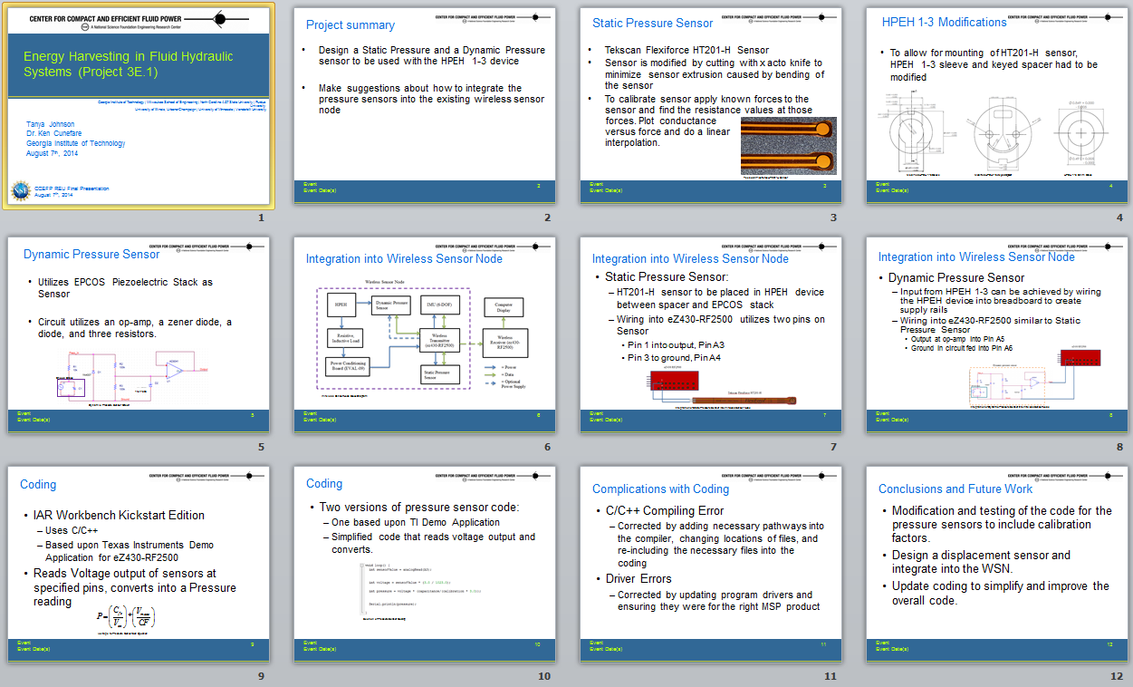
Over the course of the summer, I had to put my knowledge of EE (which isn't nonexistent, I've taken a good number of EE classes with two pertaining to electronics) in order to design a dynamic pressure sensing circuit that utilizes a component of the HPEH devices to provide the pressure sensing and a second sensor, a static pressure sensor. The static sensor utilizes and off-shelf sensor base that is integrated into an overall circuit that was suggested by the manufacturer. Both of the circuits can be optimized, and should be optimized, in the future to provide a better output voltage. The static pressure sensor utilizes a resistance based sensor that will be wired into the requisite circuit then connected into the WSN. The dynamic pressure sensor utilizes a zener diode, a diode, three resistances, and an op-amp all of which can be seen in the circuit diagram below. Essentially all of the components other than the op-amp are included in the circuit to ensure that the op-amp will not overload, as (in my experience destroying op-amps and diodes in electronics labs, diodes smell awful never burn out a diode) it is not advised or an enjoyable experience to be had. Future students involved with this WSN project will be optimizing the circuits, especially the resistor values, to better improve the circuit.

A snapshot of my powerpoint presentation can be seen below. I didn't make a poster, but I did a presentation and am presently working on completing a few reports (a final report and then a progress report on one of the HPEH devices), along with creating a three paragraph capstone summary to try and get a group of EEs to work on the WSN and the coding.
I can't believe that it's the end of the program already. Summer went by quickly, which is a shame. Anyway, I hope all y'all had a great experience with your programs (and by reading your blogs, it looks like you did) and that everyone has safe travels back home. And, of course, that everyone keeps in touch.
Now, onto my final report on my project. Unfortunately I cannot disclose some of what I've done outside of the work I did on the dynamic and static pressure sensors due to the fact that it is propriety with a company and I've signed an NDA. So, I'll just stick to the proof-of concept sensors I was working on and how that turned out, though I did do work on other things over the course of the summer. A large portion of my research was done on the HPEH devices themselves, which I cannot discuss, and the other portion was working on the design of a dynamic and static pressure sensor circuits which would then be integrated into a wireless sensor network (WSN). So I'll be sticking to the WSN and the pressure sensors, which went fairly well and the presentation I did today on them went well.
Over the course of the summer, I had to put my knowledge of EE (which isn't nonexistent, I've taken a good number of EE classes with two pertaining to electronics) in order to design a dynamic pressure sensing circuit that utilizes a component of the HPEH devices to provide the pressure sensing and a second sensor, a static pressure sensor. The static sensor utilizes and off-shelf sensor base that is integrated into an overall circuit that was suggested by the manufacturer. Both of the circuits can be optimized, and should be optimized, in the future to provide a better output voltage. The static pressure sensor utilizes a resistance based sensor that will be wired into the requisite circuit then connected into the WSN. The dynamic pressure sensor utilizes a zener diode, a diode, three resistances, and an op-amp all of which can be seen in the circuit diagram below. Essentially all of the components other than the op-amp are included in the circuit to ensure that the op-amp will not overload, as (in my experience destroying op-amps and diodes in electronics labs, diodes smell awful never burn out a diode) it is not advised or an enjoyable experience to be had. Future students involved with this WSN project will be optimizing the circuits, especially the resistor values, to better improve the circuit.
Along with the design of the sensors, they had to be integrated into the WSN and then coded. The integration involved a slight redesign of the a HPEH device to accommodate the Flexiforce sensor, but I cannot discuss the intricacies of the redesign. Along with discussing a way to allow the HPEH to power both a power optimization circuit and the dynamic sensor, which can be done by use of voltage rails. One of the components of the WSN will also be used to create voltage rails to power the Flexiforce sensor, an IMU and thermistor that were previously designed, and the op-amp used in the dynamic sensor (if needed, as it may not need those voltages to turn the op-amp on, that is just a just-in-case scenario). All of the sensors will be wired into the WSN and then coding was done in order to properly read and convert voltages into pressures.
The coding was a pain and the program consistently had the same errors despite my fixing them (repeatedly) and some runs they would work, others they wouldn't. So that was extremely frustrating, but all in all the coding went okay, the code should work as expected due to how it is just reading an output at a pin and converting. I didn't get around to calibrating the pins, so there are some variables left in the coding but I have left in depth notes about what each variable means and how to modify the code, though it is a rather straight-forward code.
A snapshot of my powerpoint presentation can be seen below. I didn't make a poster, but I did a presentation and am presently working on completing a few reports (a final report and then a progress report on one of the HPEH devices), along with creating a three paragraph capstone summary to try and get a group of EEs to work on the WSN and the coding.
Future plans for the proof-of concept WSN is to design a displacement sensor and to improve upon the coding, hopefully making it more accurate and to actually get IAR to work properly. Which is why Dr. C wants to try and get some EEs or CEs involved as they should have a stronger coding background in C or C++. Ultimately the WSN and all of the sensors will be integrated and tested on GT's test rig and possibly with one of the test rigs at Purdue, which would be really cool.
What I'm taking away from this experience was that I do want to go to Grad School (good thing I figured that out now, since I need to apply within the next few months) and that I'm fairly certain I want to go into an acoustics and thermofluids related field, possibly with regards to energy maybe not but I definitely do what to consider pursuing this kind of acoustics work. Along with how to put together an indepth report, presentation, and (as I was assigned this today) a possible Capstone summary which I need to figure out how to write. Along with how to communicate through emails and to improve my communication skills and research skills.
- Tanya
Wednesday, August 6, 2014
Project Summary and Final Post
Hi all,
I can't believe that the ten weeks are almost over! I'm very happy with the progress I've made on my project, though there still is much more work that could be done. Attached is my poster summarizing the work I've done this summer...

My project this summer was about the triboelectric effect in return line and tank mounted filters. The triboelectric effect is the phenomenon responsible for most everyday static electricity, and occurs in filtration systems between the filter media and the oil because of the large amount of contact between the two. Previous research at MSOE has discovered that replacing filter component materials with electrostatic dissipative (ESD) materials can greatly decrease the electrostatic charge generation in tank mounted filters, but is less effective in return line filters. My goal this summer was to determine why the ESD material worked so well in tank mounted filters, and not as well in return line filters.
One of my first theories was about the velocity of the oil through the filter media - each filter element has a different shape and size, so the velocity profiles through them would also be different. Although the data from running these tests revealed some interesting facts about charge relaxation, it didn't suggest that the different amounts of generated charge were from different velocity profiles.
My next idea focused on the electrical circuits created by the ESD materials. ESD materials have a higher resistivity than conductors, but still do allow the movement of electrons and will create an electric bond between their boundaries. The use of ESD materials in the tank mounted filter created a bond between the bulk oil in the tank and the filter media, while this connection did not exist in the return line filter. To test this theory, I inserted conductors as necessary into the return line filter system to create this bond. So far, my data suggests that this was the cause of the increased charge generation in the return line filter system!
As I mentioned before, there still is a lot of possible future work to do on this project. Firstly, the way I setup the return line filter with the added conductors changed several other variables - such as the pressure at the filter and oil flow rate. Although I have reasons to believe these wouldn't significantly influence the charge generation, it would be best to create a setup that was identical in every other way to the previous setup. Secondly, the data acquired from the first set of tests (that varied the velocity of the oil through the filter) has several interesting trends; what I'm working on now is trying to fit an equation to all of the data.
As for advice for a future REU student, I would suggest trying to stay ahead of schedule as much as possible; ten weeks sounds like a long time at the start but it goes by quickly! I think one of the biggest things I will take away from this summer is an appreciation for how big the fluid power industry is. For my REU program, I was lucky enough to be able to work in MSOE's Fluid Power Institute (FPI). Not only did I get to see the other projects at the FPI, I also got to go to several events hosted by the FPI, such as a tour of a Caterpillar hydraulics factory, and talk to many different professionals in working in fluid power. Before applying to CCEFP's REU program, I hadn't really heard about fluid power, but now I realize how exciting and diverse of a field it is!
I can't believe that the ten weeks are almost over! I'm very happy with the progress I've made on my project, though there still is much more work that could be done. Attached is my poster summarizing the work I've done this summer...
My project this summer was about the triboelectric effect in return line and tank mounted filters. The triboelectric effect is the phenomenon responsible for most everyday static electricity, and occurs in filtration systems between the filter media and the oil because of the large amount of contact between the two. Previous research at MSOE has discovered that replacing filter component materials with electrostatic dissipative (ESD) materials can greatly decrease the electrostatic charge generation in tank mounted filters, but is less effective in return line filters. My goal this summer was to determine why the ESD material worked so well in tank mounted filters, and not as well in return line filters.
One of my first theories was about the velocity of the oil through the filter media - each filter element has a different shape and size, so the velocity profiles through them would also be different. Although the data from running these tests revealed some interesting facts about charge relaxation, it didn't suggest that the different amounts of generated charge were from different velocity profiles.
My next idea focused on the electrical circuits created by the ESD materials. ESD materials have a higher resistivity than conductors, but still do allow the movement of electrons and will create an electric bond between their boundaries. The use of ESD materials in the tank mounted filter created a bond between the bulk oil in the tank and the filter media, while this connection did not exist in the return line filter. To test this theory, I inserted conductors as necessary into the return line filter system to create this bond. So far, my data suggests that this was the cause of the increased charge generation in the return line filter system!
As I mentioned before, there still is a lot of possible future work to do on this project. Firstly, the way I setup the return line filter with the added conductors changed several other variables - such as the pressure at the filter and oil flow rate. Although I have reasons to believe these wouldn't significantly influence the charge generation, it would be best to create a setup that was identical in every other way to the previous setup. Secondly, the data acquired from the first set of tests (that varied the velocity of the oil through the filter) has several interesting trends; what I'm working on now is trying to fit an equation to all of the data.
As for advice for a future REU student, I would suggest trying to stay ahead of schedule as much as possible; ten weeks sounds like a long time at the start but it goes by quickly! I think one of the biggest things I will take away from this summer is an appreciation for how big the fluid power industry is. For my REU program, I was lucky enough to be able to work in MSOE's Fluid Power Institute (FPI). Not only did I get to see the other projects at the FPI, I also got to go to several events hosted by the FPI, such as a tour of a Caterpillar hydraulics factory, and talk to many different professionals in working in fluid power. Before applying to CCEFP's REU program, I hadn't really heard about fluid power, but now I realize how exciting and diverse of a field it is!
Weeks Nine & Ten
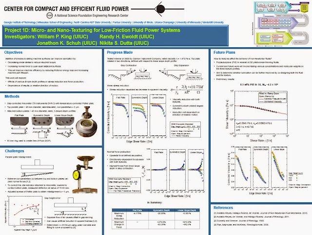
These past ten weeks have gone by so much faster than I expected, but I did get a lot done on my project in that time. After spending quite a while trying to improve our error calibration procedure (since without accurate calibrations, we have no way of judging how trustworthy our data is), we've obtained some useful results with our textured surfaces. The symmetric depth texture reduced the apparent viscosity of our most viscous fluid by 20.7%, while the linear slope depth textured gave a 6.49% reduction. Both textures also produced significantly higher normal forces than our flat plate control, with the linear slope depth texture producing the most. These results are important because stress reduction and force production are both key factors in improved lubrication, as stress reduction (or friction reduction, really) will lower the amount of energy required to move sliding machine surfaces, and increased normal force will push apparent adjacent surfaces to prevent wear and tear on machine parts.
These past few weeks, I've shifted my focus away from Newtonian oils and done some preliminary work with non-Newtonian fluids, since our ultimate goal is to be able to co-design both the surface and the fluid in order to improve lubrication even more. Our non-Newtonian results have been promising; the stress reductions seem to show the same pattern as the Newtonian fluids did, with the symmetric depth texture causing significantly more of a drop than the linear slope depth. The normal force data is a little less clear right now, as while the fluids have been producing forces even with the flat plate, the difference in force production between the flat plate and the textured plates seems largely negligible. We haven't done any repeat testing yet, however, so this may clear up more when we are able to go back and do multiple trials on the same fluid.
Overall, I'm leaving this project feeling pretty good about the progress we've made, though there's still much more to explore and I'm interested to see what direction it takes after I leave. This experience has taught me not just about fluid power and, more specifically to my project, rheology, but also about the pros and cons of full-time lab work and what I might expect if I choose to go to grad school a few years from now. I think what I have enjoyed most has been the freedom to take the research in any direction we want, while also having the constant guidance of a faculty member much more knowledgeable and experienced than I to steer and develop our thoughts. I've learned a lot from my advisor and lab group members alike, and I believe I'm going back to school with a better grasp on what to expect from my future in science and engineering.
I'm presenting to my lab group during our meeting this Friday (wish me luck!), but I've attached a photo of the poster I laid out for this project so you all can peruse it. It's been great reading your blogs this summer and getting to see my project as part of the greater narrative of fluid power that all of our work combined creates. I hope you've all had fantastic summers and have even better school years to look forward to, and thanks so much to Alyssa for putting so much into this experience and making it so worthwhile.
Best of luck with your last few days of work, and please keep in touch!
Nikita
These past few weeks, I've shifted my focus away from Newtonian oils and done some preliminary work with non-Newtonian fluids, since our ultimate goal is to be able to co-design both the surface and the fluid in order to improve lubrication even more. Our non-Newtonian results have been promising; the stress reductions seem to show the same pattern as the Newtonian fluids did, with the symmetric depth texture causing significantly more of a drop than the linear slope depth. The normal force data is a little less clear right now, as while the fluids have been producing forces even with the flat plate, the difference in force production between the flat plate and the textured plates seems largely negligible. We haven't done any repeat testing yet, however, so this may clear up more when we are able to go back and do multiple trials on the same fluid.
Overall, I'm leaving this project feeling pretty good about the progress we've made, though there's still much more to explore and I'm interested to see what direction it takes after I leave. This experience has taught me not just about fluid power and, more specifically to my project, rheology, but also about the pros and cons of full-time lab work and what I might expect if I choose to go to grad school a few years from now. I think what I have enjoyed most has been the freedom to take the research in any direction we want, while also having the constant guidance of a faculty member much more knowledgeable and experienced than I to steer and develop our thoughts. I've learned a lot from my advisor and lab group members alike, and I believe I'm going back to school with a better grasp on what to expect from my future in science and engineering.
I'm presenting to my lab group during our meeting this Friday (wish me luck!), but I've attached a photo of the poster I laid out for this project so you all can peruse it. It's been great reading your blogs this summer and getting to see my project as part of the greater narrative of fluid power that all of our work combined creates. I hope you've all had fantastic summers and have even better school years to look forward to, and thanks so much to Alyssa for putting so much into this experience and making it so worthwhile.
Best of luck with your last few days of work, and please keep in touch!
Nikita

Subscribe to:
Posts (Atom)